Bench top pulsating sensor based conductivity meter is an unconventional, high performance instrument developed at Indira Gandhi Centre for Atomic Research (IGCAR) , Kalpakkam using a new class of sensors, namely pulsating sensors. It is suitable for real-time monitoring of conductivity of aqueous solution in plants and field applications apart from its usage in chemical laboratories for analysis and quality control. The probes are compact and pipeline mountable for real-time measurement in industries. It can be interfaced through communication ports to PC or Laptop for continuous logging of data for further analysis. The meter is capable of measuring conductivity ranging from 60nS/cm to 1S/cm with an accuracy of less than 2% and displays the normalized conductivity at 25°C temperature as per international standards by the stand-alone embedded data acquisition system cum display unit. The salient feature of the meter that is unique from the commercial meters is that the probe output is directly in digital domain hence long distance transmission can be done comfortably. It is provided with user configurable temperature coefficient for a wide range of aqueous solutions from ultra pure to very high conducting solutions like sea water. The meter can be readily customized for any range of conductivity measurement as desired by the user. This is achieved by using pre-loaded probe specific calibration coefficients instead of cell constants as in commercially available meters. The calibration coefficients are pre-determined by in-house developed advanced multipoint calibration techniques.
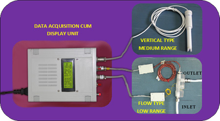
Bench top pulsating sensor based conductivity meter is an unconventional, high performance instrument developed at Indira Gandhi Centre for Atomic Research (IGCAR) , Kalpakkam using a new class of sensors, namely pulsating sensors. This can be used for measurement of conductivity of solutions over a range of 60nS/cm to 1S/cm with an accuracy of less than 2%. The meter consists of three conductivity sensors (low range, medium range and high range), a temperature sensor and a stand alone embedded electronics unit for data acquisition cum display. Low range – Flow type conductivity sensor is connected to CH-1, temperature sensor to CH-2 and medium range - Vertical type conductivity sensor or high range - U tube type conductivity sensor to CH-3. The temperature sensor is dipped in the solution of the conductivity cell for normalizing the measured conductivity at 25°C as per international standards. Conductivity of the solution is displayed in the LCD provided in the embedded system or can be logged to a PC using serial communication port. All the three input channels can be configured for desired range of measurement with the pre-loaded probe specific calibration-coefficients. The calibration-coefficients relating the output pulse frequency of the sensor, to the conductivity of solution being measured, are arrived at by an in-house developed multipoint calibration technique using a series of KCl standards and resistance comparison method.
Bench top pulsating sensor based conductivity meter is an unconventional, high performance instrument developed at Indira Gandhi Centre for Atomic Research (IGCAR) , Kalpakkam using a new class of sensors, namely pulsating sensors. Conductivity sensor consists of a Logic Gate Oscillator (LGO) powered by 5V direct current (dc) and a conductivity cell containing the solution which constitutes a part of LGO. The primary signal generated from the conductivity sensor due to mobility of ions and thus altered resistance of the cell is directly in digital domain which is transmitted to a stand-alone embedded data acquisition cum display unit. This highly simplifies the instrumentation as the hardware requirement is reduced considerably. The output of the sensor is pulse frequency which is converted to the conductivity of solution being measured by adopting a multipoint calibration technique instead of the conventional single point cell constant method. The measured conductivity normalized at 25°C as per international standards is displayed.
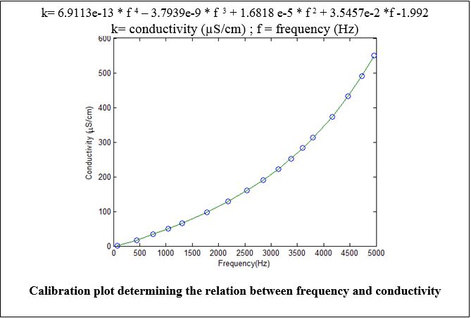
The meter consists of three conductivity sensors (low range, medium range and high range), a temperature sensor and a stand alone embedded electronics for data acquisition cum display. Low range – Flow type conductivity sensor is connected to CH-1, temperature sensor to CH-2 and medium range - Vertical type conductivity sensor or high range - U tube type conductivity sensor (as per user application) to CH-3. The temperature sensor dipped in the solution of the conductivity cell is provided for normalizing the measured conductivity at 25ºC. All the three input channels can be configured for desired range of measurement with the corresponding pre-loaded, probe specific calibration-coefficients. The calibration-coefficients relating the output pulse frequency of the sensor, to the conductivity of solution being measured, are determined by an in-house developed multipoint calibration technique using a series of KCl standards. A sample calibration plot to determine the calibration coefficients is shown for the conductivity range 0 to 600 µS/cm where the measured frequency (f) is related to the conductivity of the solution (k) , by a fourth degree polynomial equation in (f).
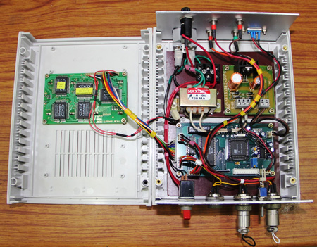
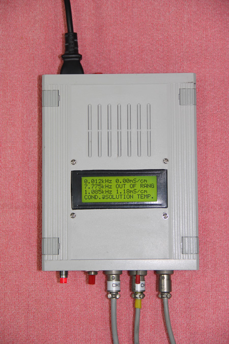
Conductivity of the solution is directly displayed in the Liquid Crystal Display (LCD) provided in the embedded system or can be logged to a PC using serial communication port. The embedded display board consists of a three channel counter, microcontroller, LCD and an interface to communicate through RS232 port to PC. The pulses received from sensor are sent to a 16 bit counter interfaced with embedded controller, which counts the pulses for a fixed duration of time (gate time). The frequency is calculated by microcontroller, by registering the number of pulses and gate time. The microcontroller then converts the frequency to the conductivity of the solution using the pre-loaded appropriate calibration coefficients. Both frequency and conductivity are displayed in LCD and stored in a nonvolatile memory with time stamp. The stand-alone system is configured through a PC via serial port interface.
| Uniqueness | Pulsating type conductivity and temperature probe. |
| Range of measurement | Conductivity Range: 60nS/cm to 1S/cm Flow type Conductivity probe – 60nS/cm to 5µS/cm Vertical type Conductivity probe - 5µS/cm to 1000µS/cm U tube type Conductivity probe – 1mS/cm to 1S/cm Temperature Range: 25°C to 45°C |
| Temperature normalization | Provision for temperature normalization (Display of conductivity is normalized at 25°C when temperature probe is connected). One input channel will be exclusively used for temperature probe. When it is required to measure conductivity at solution temperature, the temperature probe may be disconnected from the measuring instrument. |
| Display | Provided with a LCD display (4 x 20 characters) for display of conductivity in µS/cm or mS/cm and temperature in °C. |
| Probe output | A train of rectangular pulses of 5V amplitude. |
| Cable | 5-core shielded signal cables with 5-pin Gilard connectivity are used. |
| Power Supply | Mains power supply (230V AC, 50 Hz); but unit needs only 5 V DC power supply for signal generation. |
| Signal processor | Pulse counting in channels 1, 2 and 3, conversion of frequency to conductivity in CH-1 & CH-3 and conversion of frequency to temperature in CH-2 and normalization of conductivity to 25°C. |
| Precision | Relative standard deviation is ≤1.0 % for all three ranges of conductivity probes. |
| Accuracy | < 2.0 % in the entire measurement range. |
| Resolution | Capable of monitoring conductivity shift by ≤ 0.02 µS/cm in the low range (60 nS/cm to 5 µS/cm), 0.1 µS/cm in medium range (1 to 1000 µS/cm) and 0.1 mS/cm in high range (1mS/cm to 1 S/cm). |
| Response time | < 1 sec |
| Calibration | Multipoint calibration using standard KCl solutions & resistance comparison method. |
| Signal transmission | High precision in measurement, direct digital signal from probe head, and transmission of signal to a long distance (~ 100 meter) without losing precision in measurement. |
| Data acquisition | Gate time and interval time user fed as per desired application |
| Operating temperature | Room temperature |
Interested parties with Engineering & Scientific knowledge, good financial background and adequate experience of products manufacturing & fabrication with technical capability in the area of interested technology and having or interested in setting –up facilities for production would be preferred.
Send your Technology Transfer Application form duly filled and signed along with a Demand Draft/Bankers cheque of Rs. 500/- (for Indian entities) or US $50/- (for foreign entities) drawn in favour of “Accounts Officer, IGCAR” as application processing fee on following address:
Note:Applications without processing fee as applicable above of Rs. 500/- or US $50/- for each technology will not be considered.
Click here for Technology Transfer Application Form